Analysis of the Effect of the Solid-Brick Infilled Frames on the Behavior of A Hybrid System of Moment Resistance Frame, Shear Wall, and Infilled Frame Along High Concrete Structures
Mehdi Shekarbeigi1 * and Hooshang Shekarbeigi2
1
Faculty of Engineering,
Razi University of Kermanshah,
Iran
2
Faculty of Engineering,
Azad University,
Shoushtar,
Iran
http://dx.doi.org/10.12944/CWE.10.Special-Issue1.95
This paper is to investigate the benefits of a new structural system (hereafter it is referred as “Ultra Hybrid System”) in high concrete buildings relying on the compound performance of the moment resistance frame, shear wall and infilled frame. In this case, the Ultra Hybrid System takes the advantage of the moment resistance frame and shear wall up to the height, where the wall performance reaches zero, while it is applied the infilled frame along with it. It is studied the system behavior based on using concrete-brick infilled frames in the upper floors to find out the interaction between the shear wall and infilled frame. Then, it is compared displacement, relative floor displacement, base shear, axial column loads in a hybrid system of the moment resistance frame and shear wall and the Ultra Hybrid System of the moment resistance frame, shear wall, and infilled frame. In this study, ETABS 2000 software package )Barkhordari et al., 2001) is used to model the system in compression diagonal mode. Finally, the results are presented in diagrams and tables.
Copy the following to cite this article:
Shekarbeigi M, Shekarbeigi H. Analysis of the Effect of the Solid-Brick Infilled Frames on the Behavior of A Hybrid System of Moment Resistance Frame, Shear Wall, and Infilled Frame Along High Concrete Structures. Special Issue of Curr World Environ 2015;10(Special Issue May 2015). DOI:http://dx.doi.org/10.12944/CWE.10.Special-Issue1.95
Copy the following to cite this URL:
Shekarbeigi M, Shekarbeigi H. Analysis of the Effect of the Solid-Brick Infilled Frames on the Behavior of A Hybrid System of Moment Resistance Frame, Shear Wall, and Infilled Frame Along High Concrete Structures. Special Issue of Curr World Environ 2015;10(Special Issue May 2015). Available from: http://cwejournal.org?p=660/
Download article (pdf)
Citation Manager
Publish History
Introduction
In high concrete buildings, it is important to control the lateral seismic loads. So, it is utilized the hybrid structural systems to restrain it, such as the system of moment resistance frame and shear wall, which is modeled in this study.
However, it has several disadvantages, including negative performance of shear wall with the structure height, so that it provides a good performance up to a limited height in this system. In the study, it is utilized the shear wall up the maximum possible height, where its performance reaches zero, and at that height, it is substituted with concrete-brick infilled frames (Ultra Hybrid System).
To obtain desirable results by placing the infill frames coaxially with the column axis along the structure height, it is examined two modes of the infill frame plane arrangements: (1) Placement of infill frame along the shear wall; and (2) fixed shear wall in situ and tending the infill frame toward the structural center of mass. Later, it is observed the performance of Ultra Hybrid System with the thickness of infill frames in terms of several factors, including relative floor displacement (drift). Because of the regularity of the structure in plane and also elevation of 50 meters in the models studied, the dynamic spectral analysis is used.
Structural Systems
Three system types are developed to restrain the lateral loads affecting a reinforced concrete structure as follows:
- Moment resistance frame system
- Shear wall system
- Hybrid system (moment resistance frame + shear wall)
The most efficient system to restrain the lateral seismic loads is hybrid system of moment resistance frame and shear wall. This establishes on the performance of shear wall to absorb the lateral loads, while the frame provides for neutralizing the vertical loads.
In tall buildings, lateral displacement of the building is so large at a certain height that rigidity becomes the critical controlling element. Rigidity is mainly dependent on the type of structural system. Additionally, the efficiency of any particular system is directly linked to the amount of materials used. Therefore, it is necessary to obtain the minimum rigidity with minimum weight for optimization of certain spatial condition. As a result, it is developed various structural systems for determined heights, including the Ultra Hybrid System of the moment resistance frame, shear wall, and infilled frame in the same direction, which will be later discussed.
Assumptions and Modeling
Since the results of the models are compared together, they should be equally loading. In addition, the models are studied by spectral dynamic analysis (Road, Housing, and Urban Development Research Center ., 2005) considering the height of over 50 meters according to the 2800 regulation of Iran. In this study, two categories of buildings are assumed with 20 and 25 floors and a skeletal system of moment resistance frame and reinforced shear walls with special ductility, as well as joists and filler block ceiling with a thickness of 25 cm. Note that these models lack any irregularity, while it isn’t seen no changes in the panel zone and plate of lateral load-bearing components. In the models, ST denotes the number of floors, and D and MG, respectively represent a structure with shear wall and a structure with infill frame, while the bracketed figure indicates the thickness of infill frame.
According to the zoning of earthquake risk, the study site is classified as high relative risk zone. The buildings are considered with the intermediate importance in the same group. Additionally, it is assumed second-type land [based on the land categorization of 2800 regulation] with the period of 0.5 sec and behavior factor of the building R = 11 associated with the studied system. With the models, it is utilized the shear wall up the maximum possible height, where its performance reaches zero (bending turning point: (d2y/dz2 =0 ), and at that height, it is substituted with concrete-brick infilled frames (Figure 1) [Coull A et al ., 1996].
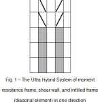 |
Figure 1: The Ultra Hybrid System of moment resistance frame,shear wall, and infilled frame (diagonal element) in one direction Click here to View figure |
It is considered two different frame arrangements for the Ultra Hybrid System: (1: infill frames are placed along the shear wall; and (2: fixed shear wall in situ and tending the infill frame toward the structural center of mass (Figures 2 and 3).
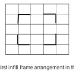 |
Figure 2: First infill frame arrangement in the plane Click here to View figure |
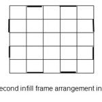 |
Figure 3: Second infill frame arrangement in the plane Click here to View figure |
In this study, ETABS 2000 software package is used to model the infill frames in compression diagonal mode, where the diameter of equivalent bar is equal to the thickness of infill frame tinf, while the diagonal length is denoted by rinf. So, the effective width is given as follows:
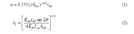
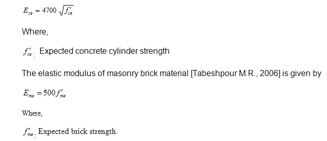
As show in Figure 3, the equivalent compression diagonal bar is replaced with the infill frame. Note that the infill frame of Ultra Hybrid System is generally made of concrete and brick. The elastic modulus of the reinforced concrete frame is
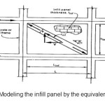 |
Figure 4: Modeling the infill panel by the equivalent bar Click here to View figure |
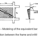 |
Figure 5: Modeling of the equivalent bar and interaction between the frame and infill frame Click here to View figure |
Results and Discussion
In this study, two categories of buildings are modeled with 20 and 25 floors using the hybrid and ultra hybrid systems. Then, the models are compared in terms of several factors, including the relative floor displacement. The results are shown in diagrams and tables. Later, it is observed the performance of Ultra Hybrid System with the thickness of infill frames, and the infill frame arrangement in the plane. (Behrouyan et al ., 2007)
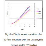 |
Figure 6: Displacement variation of a 20-floor structure with the Ultra Hybrid System under EY loading Click here to View figure |
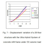 |
Figure 7: Displacement variation of a 20-floor structure with theUltra Hybrid System of concrete infill frame under EX seismic load Click here to View figure |
The above diagram shows five structural displacement modes using different systems. It is concluded that it is seen complete conformity between the structural displacements in two modes of using a frame with thicknesses of 20 cm and 30 cm based on the Ultra Hybrid System (moment resistance frame + shear wall + infilled frame), while the structural displacement reduction (%) isn’t significantly different with the hybrid system (moment resistance frame + shear wall). This indicates that there isn’t achieved a significant difference by changing the thickness of infill frame in the Ultra Hybrid System.
Table 1: Displacement reduction (%) of a 20-floor structure using the concrete infill frame
| Displacement Reduction (%) | Structural Model |
| 20% | MG(20) |
| 23% | MG(30) |
| 4% | First Model:D+MG(20) |
| 12% | D+MG(20)Second Model: |
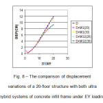 |
Figure 8: The comparison of displacement variations of a 20-floor structurewith both ultra hybrid systems of concrete infill frame under EY loading Click here to View figure |
As presented in the Table 1, the displacement reduction (%) of second model (fixed shear wall in situ and tending the infill frame toward the structural center of mass) is 8% higher than first one using the ultra hybrid system in a 20-floor structure. It illustrates the higher efficiency of second model based on utilization of the Ultra Hybrid System. The displacement reduction (%) of a 25-floor structure is presented in Diagram 2 and Table 2, which shows 3% and 7% respectively for the first and second models. ( Behrouyan et al ., 2007)
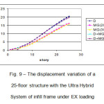 |
Figure 9: The displacement variation of a 25-floor structurewith the Ultra Hybrid System of infill frame under EX loading Click here to View figure |
Table 2: Displacement reduction (%) of a 25-floor structure using the concrete infill frame
| Displacement Reduction (%) | Structural Model |
| 21% | MG(20) |
| 23% | MG(30) |
| 3% | First Model:D+MG(20) |
| 7% | Second Model:D+MG(30) |
Table 3: The drift reduction (%) of a 25-floor structure
| Drift Reduction (%) | Structural Model |
| 18% | MG(20) |
| 17% | MG(30) |
| 5% | First Model:D+MG(20) |
| 39% | Second Model:D+MG(20) |
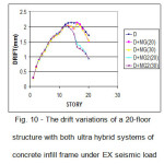 |
Figure 10: The drift variations of a 20-floor structure with both ultrahybrid systems of concrete infill frame under EX seismic load Click here to View figure |
Figure 10 illustrates the drift variations of a 20-floor structure with both ultra hybrid systems. As shown, there is observed a similar drift up to the 10th floor, where it is seen a significant difference between two model. The drifts of first and second models are respectively 10% and 28% (See Table 3). Also, as seen of ST D+MG(20) and ST D+MG(30) curves, increasing the thickness of infill frame has quantitatively affected the performance of the Ultra Hybrid System.
Table 4: The drift reduction (%) of a 25-floor structure
| Drift Reduction (%) | Structural Model |
| 17% | MG(20) |
| 17% | MG(30) |
| 10% | First Model:D+MG(20) |
| 28% | Second Model:D+MG(20) |
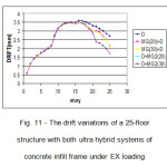 |
Figure 11: The drift variations of a 25-floor structure with bothultra hybrid systems of concrete infill frame under EX loading Click here to View figure |
The above diagram shows the drift variations associated with the first and second models of ultra hybrid system using two different frame thicknesses of 20 cm and 30 cm. As illustrated, there is seen a similar drift up to the 15th floor, where it is observed a significant difference between two model. Note that the shear walls are replaced with infill frames at the 15th floor. On the other hand, there is tangible difference in drift of ultra hybrid system and hybrid system. However, the second model (tending the infill frame toward the structural center of mass) shows the lowest drift. In addition, the drift reductions (%) of first and second models are respectively 28% and 10%, which indicates a better structural performance of former. In the other words, it is the most optimal mode compared other structural systems in terms of drift reduction.
The results ultra hybrid system with brick infill frame suggest that there isn’t significant difference between brick and concrete infill frames associated with the displacement and relative floor displacement (drift).
Conclusions
Later, it will be presented the results of analytical studies on the limited structural models. They are modeled using the hybrid system and ultra hybrid system. Note that it should be caution to generalize the results.
- As results of dynamic analyzing the ultra hybrid system (moment resistance frame + shear wall) indicated, the structural performance reaches zero at a certain height, where it is substituted with concrete\brick infilled frames. This improves the structural performance in terms of relative floor displacement, base shear, and axial column loads; in some case, it reduces the floor drift by 40%.
- The second model of Ultra Hybrid System (tending the infill frame toward the structural center of mass) shows a much better performance compared with the first one. So, it is recommended to utilize the first model for concrete structures.
- It should be noted that increasing the thickness of infill frame has quantitatively affected the performance of the Ultra Hybrid System associated with displacement and relative floor displacement. So it is recommended to apply the thickness of 20 cm for brick\concrete frames.
As the analysis of the ultra hybrid system with concrete\brick infill frame shown, there isn’t significant difference between brick and concrete infill frames associated with the relative floor displacement; thus, it could be used both to implement the ultra hybrid system.
- Note that the results are obtained, where the infill frames are placed coaxially with the column, which is appeared as the most optimal mode.
References
- Road, Housing, and Urban Development Research Center, “Regulations of Designing Buildings against Earthquake”, 3rd ed (2005)
- Coull A., “Tall Building Structures: Analysis and Design”, translated by Haji Kazemi H., Publications of Ferdowsi University of Mashhad (1996)
- Tabeshpour M.R., “Practical Conceptual Interpretation of Regulations of Designing Buildings against Earthquake”, Ganj Honar Publications (2006)
- Barkhordari M., Baji H., and Hashemi J., “Three-Dimensional Analysis and Design of Building Structures: A Reference to ETABS 2000 Software”, Publications of Hormozgan University (2001)
- Moghadam H., “Seismic Design of Brick Buildings”, Publications of Sharif University of Technology, 1st ed. (1994)
- Behrouyan M. and Shekarbeigi M., “Analysis of Hybrid Structural System of the Moment Resistance Frame, Shear Wall and Infilled Frame in one Direction”, M.S. Thesis, Faculty of Engineering, Islamic Azad University- Central Tehran Branch (2007)
- Behrouyan M. and Gharavis H., “Study of the Impacts of Infilled Frames on the Seismic Behavior of Asymmetric Concrete Structures with Moment Resistance Frame”, M.S. Thesis, Faculty of Engineering, Islamic Azad University- Central Tehran Branch (2006)